Marcelo Alcantara Holanda +
By the end of this chapter the reader should be able to:
Understand the physiological spontaneous respiratory cycle;
Understand and classify respiratory cycles during mechanical ventilation ;
Understand the basic modes of mechanical ventilation;
A/C, VCV - Assisted/Controlled, Volume Cycled Ventilation
A/C, PCV - Assisted/Controlled, Pressure Controlled Ventilation (time cycled)
SIMV - Synchronized Intermittent Mandatory Ventilation
PSV - Pressure Support Ventilation
One can define ventilatory mode as the process by which the mechanical ventilator determines, either partially or fully, when the mechanical breaths are to be provided to the patient, thus determining the breathing pattern of the patient during mechanical ventilation. For the purposes of classification, there is still a need for an international consensus or standardization as there remains non-standardized and confusing terminology. This is compounded by the adoption of different commercial brand names by manufacturers of mechanical ventilators, often for modes with similar functionality. In 2010, about 54 names of respiratory "modes" were available in 49 brands of mechanical ventilators. This scenario creates challenges in the adequate training of healthcare professionals, at times leading to the inappropriate management of the most common ventilation modes, and even endangering the lives of patients undergoing mechanical ventilation.
This chapter presents a simple and logical definition of commonly used basic ventilatory modes. It is divided into 4 parts: the concept of the spontaneous physiological respiratory cycle; the respiratory cycle provided by the mechanical ventilator; commonly used ventilation modes, their settings and limitations; and finally, the prospects for new methods that have been recently made available. To facilitate the explanation of the different cycles or modes, figures were created using the xlung simulator. These are based on the equation of the motion of gases in the respiratory system.
- The spontaneous physiological respiratory cycle
- The Respiratory Cycle During Mechanical Ventilation
- Controlled Cycles
- Assisted Cycles
- Basic ventilatory modes
- A/C Modes: VCV and PCV
- PSV Mode
- SIMV with PS Mode
- Prospects for New Ventilatory Modes
- Bibliography
Chatburn RL. Classification of Ventilator Modes: Update and Proposal for Implementation. Respiratory Care, 2007; 52(3): 301-323.
Branson R., Chatburn RL, Hess D. Respiratory care equipment, 2nd ed. Philadelphia: Lippincot, 1998.
Chatburn RL, primiano FPJr. A new system for understanding modes of mechanical ventilation. Respir Care 2001; 46(6):604-621.
Carvalho CRR - Ventilação Mecânica. Volume I – Básico. Clínicas Brasileiras de Medicina Intensiva, São Paulo: Ed. Atheneu, 2000
Carvalho CRR - Ventilação Mecânica. Volume II – Avançado. Clínicas Brasileiras de Medicina Intensiva, São Paulo: Ed. Atheneu, 2000
Figure 1 shows the physiological, or spontaneous, respiratory cycle without support from a mechanical ventilator.
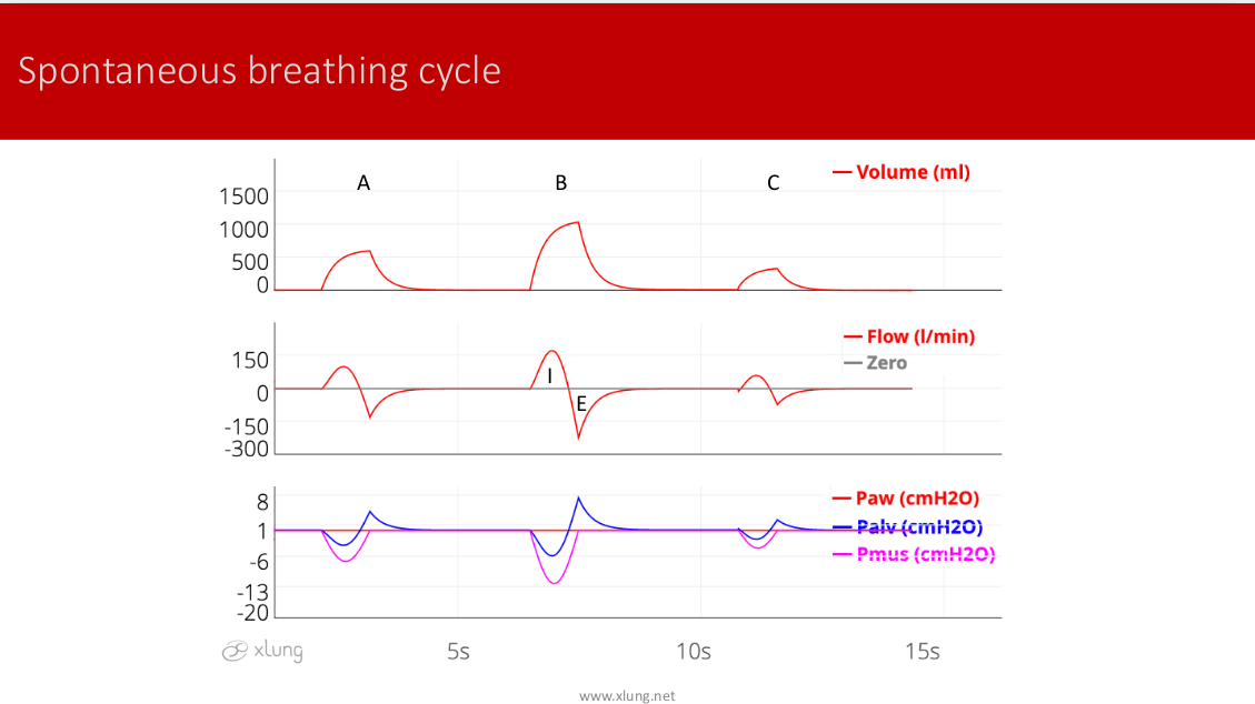
Figure 1. Spontaneous breathing cycle. Variations of the respiratory muscle effort (Pmus) influence the alveolar pressure making it negative during inspiration. Therefore, it generates inspiratory flow. Tidal volume is the result of flow x time. When the respiratory muscles relax, alveolar pressure increases, and expiratory flow begins passively due to lung elastic recoil pressure. A- Normal effort, B-Intense effort, and C-Weak effort. I-Inspiration and E-Expiration
In this figure, inspiratory muscle effort, represented by Pmus, varies in intensity and duration in each cycle. According to Boyle's law, to expand the volume of the chest cavity the Pmus reduce the pressure of alveolar gas. This is represented by the alveolar pressure in blue, with the values dipping slightly below what is considered the zero reference value of atmospheric pressure. This generates a pressure gradient between the proximal airways (nose and mouth) and the lung parenchyma, resulting in a flow of air from the external environment into the alveoli through the airways generating the inspiratory flow. The shape of the wave and the intensity of this flow is determined by this pressure gradient and the airway resistance. Over time, a certain volume of air is blown into the alveoli, defined as tidal volume (VT), calculated as tje integral of flow x time. As the alveoli are inflated and the pulmonary parenchyma is stretched, the elastic lung tissue pressure rises in direct proportion to the inspired tidal volume divided by compliance of the lungs and chest wall.
The inspiration time is the interval between the beginning of the intake of air to when the maximum value of VT is reached. With the gradual decline of Pmus at the end of inspiration, followed by the complete relaxation of the inspiratory muscles, a priorly negative alveolar pressure progressively rises to the point where it exceeds the pressure of the proximal airways, which remains at zero. At this point, the wave flow is reversed and expiration from the lungs to the external environment begins. Normally, the wave of expiratory flow has a negative value. The exhaled air is passively driven by alveolar pressure that is elevated in the final stage of inspiration due to increased lung elasticity and the relaxation of the inspiratory muscles. Exhalation takes place according to the time constant of the respiratory system, consisting of the product of Raw x Cst until the moment that the alveolar pressure again equilibrates with the airway pressure and the flow ceases.
The expiratory time is calculated as the interval from the beginning of the expiratory flow to the beginning of the next inspiration. This process is controlled by the brain’s respiratory or pneumotoxic center located in the medulla. This is determined by a complex set of mechanisms involving, among other elements, afferent neural impulses from peripheral and central chemoreceptors, mechanoreceptors in the lungs and chest wall, the cerebral cortex and other regions of the central nervous system. It is this intricate mechanism of the respiratory cycle that operates the human being's "natural ventilator". Not surprisingly, ventilation support still presents major limitations despite great technological advances in recent decades.
Mechanical ventilation is essentially a process that replaces all or part of the action of the inspiratory muscles as well as the neural control of breathing. Two basic types of respiratory cycles can be defined. In the first type, the ventilator "controls" the entire inspiratory phase, or totally replaces the respiratory muscle effort and neural control of the patient. This cycle is referred to as a “controlled” cycle. In the second type, the venitlator only assists the inspiratory muscles that are active and is referred to as an “assisted” cycle. Some authors use the term "spontaneous cycle" to refer to that which occurs during supply of pressure support (PS). Instead, the term “assisted” is used here to designate the second type of cycle in order to be consistent with the above definition. The term “spontaneous cycle” is used here only for physiological breathing.
In addition to these two major divisions, the cycle of the mechanical ventilator can also be classified according to variables that are controlled during inspiration: these include time, flow, volume or pressure. On the other hand, it could be a combination of two or more of these. For example, a “controlled cycle” could be called VCV (Volume Cycled Ventilation) if it is programmed to end or "cycle" when it reaches a predetermined value of tidal volume (VT) -- or it could be a timed cycle, called PCV for Pressure Controlled Ventilation.
Figures 2 and 3 show Volume Controlled Cycles
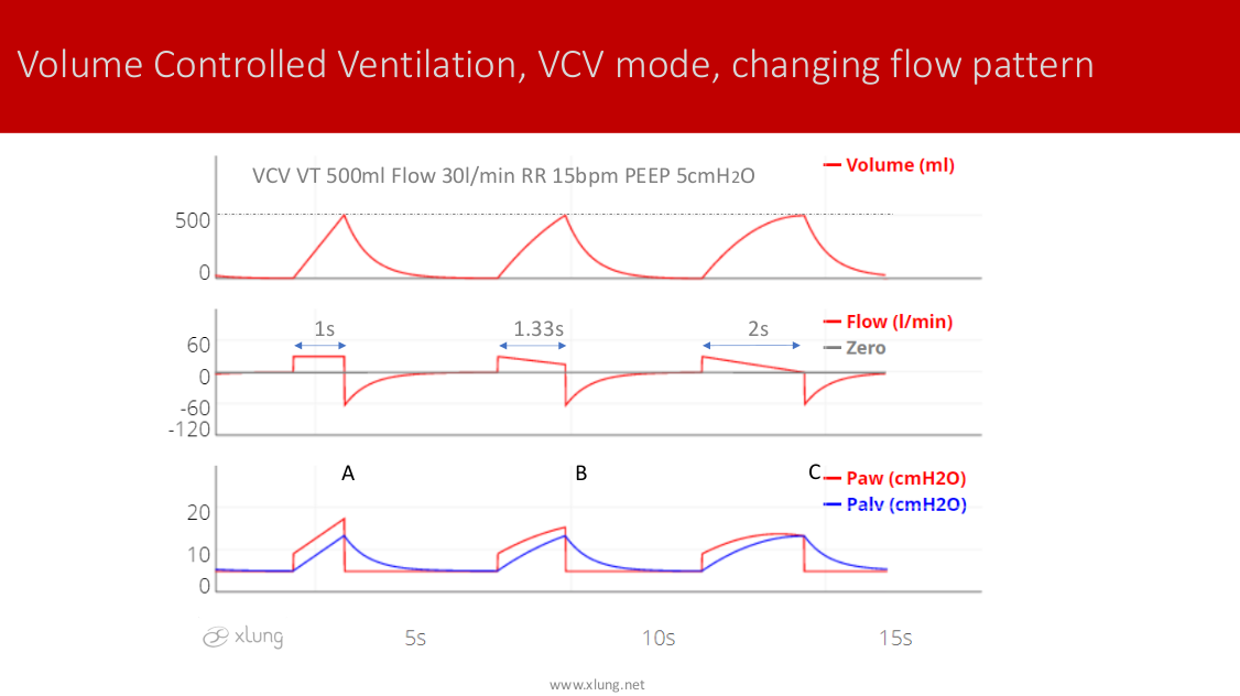
Figure 2. Volume Cycled or Controlled Ventilation (VCV Mode). Controlled respiratory cycles: tidal volume (VT), inspiratory flow (A, square type; B, decelerating to 50%, C, decelerating to 0%). Inspiratory time increases accordingly. The alveolar pressure (in blue) did not vary because it was determined by a fixed VT (dashed line). The expiratory time reduces depending on the inspiratory time and the set RR. See the text for further details.
Figure 2 presents three cycles of VCV. In this situation, the respiratory muscle effort, represented by the Pmus, is zero. The VT was set to 500ml (0.5l). In addition to the VT, the intensity and the wave pattern of flow is determined by the operator of the ventilator. Thus, the inspiratory time is predefined, based on the ratio of VT/flow. In the first cycle, with a constant flow, or square type, set to 60l/min (1 l/s), the inspiratory time corresponds to the division of 0.5l by 1l/ s, or 0.5s. In the second cycle, the flow was reduced by half or 30l/min (0.5l/s) doubling the Ti to 1s. In the third cycle, not only was the maximum flow reduced by half, but the wave pattern of flow was adjusted, on a descending slope, reducing it to 50% of its initial value. This adjustment resulted in an average flow of 22.5l/min or 0.375l/s and thus an even longer Ti, 0.5l/0.375l/s or 1.33s. Note that the airway pressure (in red) but not the alveolar pressure (in blue) varies according to adjustments of flow, since this influences the resistive pressure of the airways. The alveolar pressure remains the same in the three cycles since the VT, its principal determinant, is the same in all three cycles. As in the spontaneous cycle, the air is passively exhaled by the increase of the pulmonary elasticity (alveolar pressure) by simply having the ventilator prevent the entry of air, and opening the expiration valve. Note that the expiration proceeds until the alveolar pressure returns to a predetermined value, in this case, above zero as determined by the setting of a positive end expiratory Pressure or PEEP.
Figure 3 shows the impact of the VT settings on the Ti and the airway pressure in controlled VCV cycles.
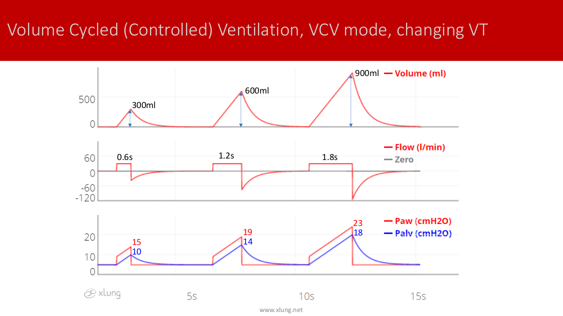
Figure 3. Volume Cycled Ventilation (VCV mode). Controlled respiratory cycles: Changes in VT 300ml, 600ml, and 900ml with the constant inspiratory flow (square pattern, 30l/min), PEEP 5cmH2O. Inspiratory times and both airway and alveolar pressures increase with higher VTs.
In Figure 3 the operator of the ventilator modifies the VT and maintains a constant flow. The pressures of the airway opening and lung volume vary in direct proportion to changes in the VT. Note that the Ti also varies (Ti = VT/flow). In practice, the VCV cycling is very easily adjusted by simply defining the target VT. For example, 8ml/kg of predicted body weight, and adjusting the flow to guarantee a Ti of approximately 0.6s to 1.2s, depending, of course, on the recommended specific ventilation strategy for a particular patient.
Figures 4 and 5 show PCV CYCLES.
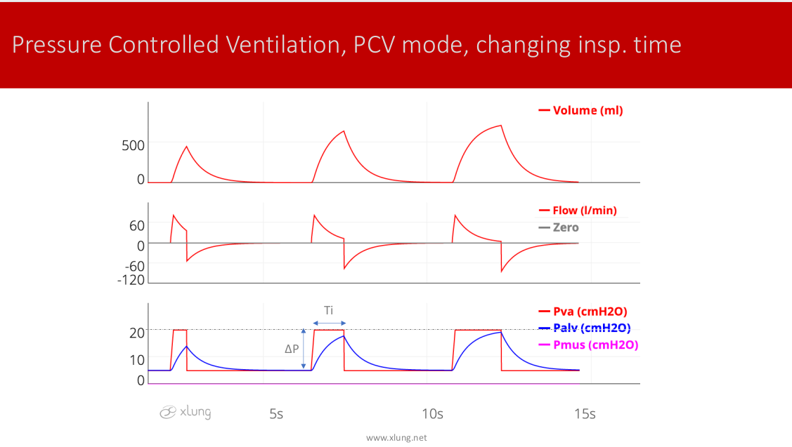
Figure 4. Pressure Controlled Ventilation (PCV), controlled cycles. The main ventilator settings are the inspiratory airway pressure applied above PEEP (ΔP) and the inspiratory time (Ti). Ti has been modified in the first, second, and third cycles to 0.5, 1.0, and 1.5 seconds, respectively. Note the significant increase in VT in the second cycle compared to the first one and the minimum additional increase in the third cycle. The ΔP applied above PEEP was kept constant at 15cmH2O, generating a maximum airway pressure of 20cmH2O (dashed line). The difference between the airway pressure of the ventilator and the alveolar pressure of the patient’s lungs determines the inspiratory flow, which always presents a pattern of deceleration rather than constant.
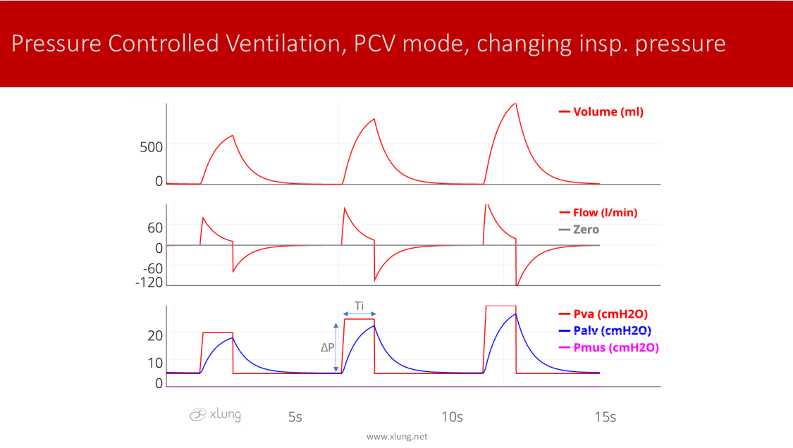
Figure 5. Pressure Controlled Ventilation (PCV) controlled cycles. Ti was set to 1s while the ΔP applied above PEEP was modified to a sequence of 15, 20, and 25cmH2O. Note that the VT and alveolar pressures rise due to the higher ΔP.
One can observe that the determination of VT in cycles with constant airway pressure can be done indirectly, by varying the Ti (in Figure 4), or changing the "delta" pressure above PEEP in the airways (Figure 5), or both. It is important to note that respiratory cycles in PCV do not guarantee the values of alveolar pressure since this is determined by the relationship between the VT and the static compliance of the respiratory system. Usually one can adjust the Ti at a given value, 0.6 to 1.2s for example, and setting it the "delta" pressure above PEEP until achieving a certain desired VT.
In summary, the controlled cycles are basically the VCV or the PCV types. There are hybrid modes combining features of both types that will be covered in the chapter on new ventilation modes. At this point we can define the ventilation mode formerly called “controlled” as those that only offer controlled cycles to the patient. Obviously, purely controlled modes are no longer used because it would result in great discomfort for patients when they do use their respiratory muscles.
A more complex situation occurs when the neural command respiratory (drive) and the muscles of the respiratory system of the patient are active. In this case virtually all mechanical lung ventilators monitor the "demand" of the patient by continuous measurement of the flow and/or pressure in the ventilator circuit. This adjustment, commonly called "sensitivity" or trigger function, determines the threshold of flow or pressure variations that will be recognized by the machine as the muscular effort of the patient. A well-adjusted sensitivity is crucial for the patient to be able to trigger respiratory cycles when so desired. An adjustment to sensitivity for pressure of -1 or -2cmH2O or a flow of 2 to 5l/min is usually recommended. It is known that the ventilator triggers more easily with sensitivity to flow, although the clinical value of this feature is debatable. Figures 6 and 7 show the VCV and PCV cycles, respectively, in patients with variable muscular effort.
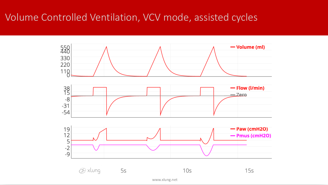
Figure 6. Assisted VCV with sensitivity to flow 3l/min. Note that the Pmus of the patient (in pink) is "negative" in the airway pressure curve. This is because the ventilator maintains the flow and the VT with no variation. Although the sensitivity is adjusted correctly and the patient can "trigger" all cycles, there is an evident lack of synchronization between the ventilator and the Patient’s demand for flow, especially when the patient increases the duration and intensity of his muscular effort.
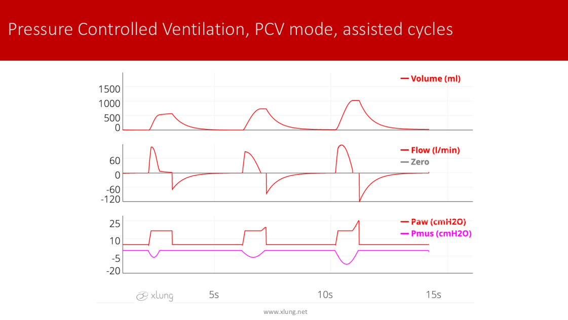
Figure 7. Assisted PCV cycles, with sensitivity to flow 3l/min. Note that the patient's Pmus (pink line) generates an increase and changes the shape of the inspiratory flow corresponding to the patient's effort and neural respiratory drive. VT and flow increase with respiratory muscle efforts, while the ventilator (mechanical) Ti remains the same.
Comparing VCV and PCV assisted cycles, there is an important difference in the response of the ventilator to the muscular demand of the patient. In PCV, the ventilation, by increasing the flow and VT in relation to patient effort, is potentially less uncomfortable. Although one of the main goals of mechanical ventilation is to relieve dyspnea and respiratory muscle effort, this type of cycle is more favorable when it is clinically desired that the patient perform respiratory muscle contractions, as is common after the first 24 to 48 hours following tracheal intubation.
Besides the assisted cycles in VCV and PCV, ventilators have a third type of cycle called Pressure Support Ventilation (PSV). The cycles assisted with PSV are similar to cycles in PCV except that the cycling mechanism is flow, rather than time. Figure 8 illustrates and explains the mechanism of cycling in PSV.
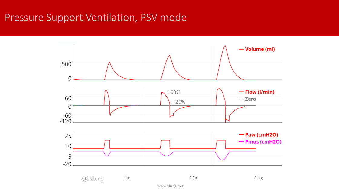
Figure 8. Pressure support ventilation (PSV) cycles with sensitivity to flow 3l/min. Cycling occurs when it reaches a certain threshold of the maximal inspiratory flow within a particular breathing cycle (cycling off criterion). Most ventilators are usually set to cycle with values between 20 to 25% of the peak inspiratory flow. Flow, VT, and Ti can all vary depending on the interaction between the patient and the ventilator.
In the PSV cycles the possibility of variability of flow, VT and Ti can potentially promote greater comfort for some patients. Also, current ventilators can provide the adjustment of the cycling threshold that can, for example, be set between 5 and 70%. Such a tool allows finer tuning of PSV cycles, especially in COPD patients with high airway resistance and normal or increased static compliance. In these cases, the Ti could remain too long due to the smallest deceleration of inspiratory flow as shown in Figure 9. In this setting it is worth remembering that the PSV as well as the PCV allow adjustments to the flow rate or speed of pressurization of the airway at the beginning of inspiration. This setting is commonly referred to as "rise time." The reader should refer to the chapter Asynchrony Patient-Ventilator for more details on the practical handling of these new technological features incorporated into the PCV and the PSV.
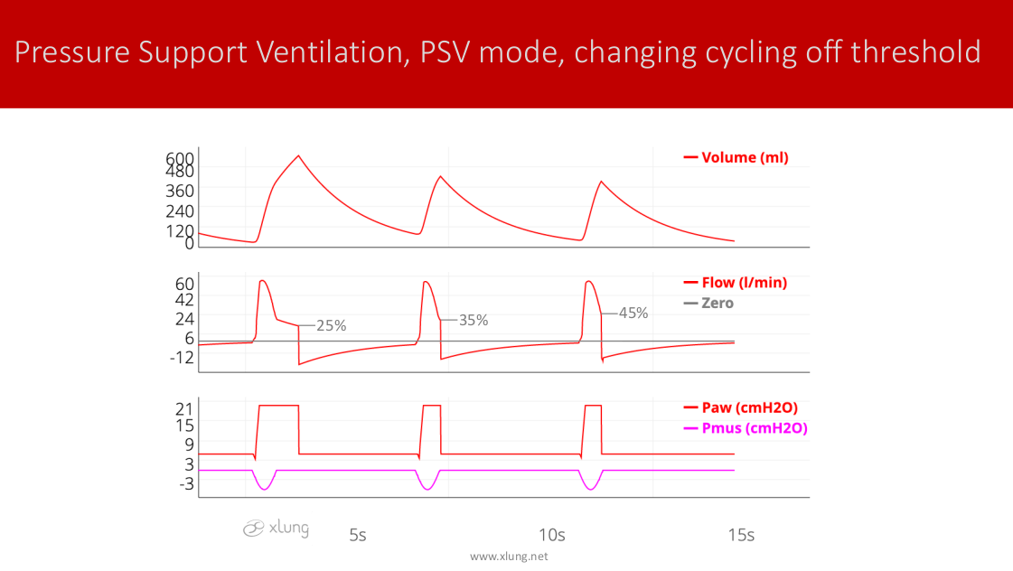
Figure 9. Pressure Support Ventilation (PSV) cycles with sensitivity to flow 3l/min. In this case, the percentage threshold for cycling was increased from 25% to 35% and 45% in sequence. Observe the impact of this adjustment on the Ti, the flow curve, and the VT. Increasing the threshold reduces the Ti and VT, which may be advantageous in patients with COPD and lung hyperinflation.
Based on the types of respiratory cycles that are offered to the patient, three basic ventilatory modes can be considered. These are: Assist/Control ventilation (A/C), Pressure Support Ventilation (PSV) and Synchronized Intermittent Mandatory Ventilation (SIMV) with PS, a hybrid mode of the first two.
The A/C mode is characterized by offering controlled and/or assisted cycles, depending on the settings programmed for the minimum respiratory rate (RR) delivered to the patient. In turn, the A/C mode can offer cycles in VCV or PCV. Thus there are A/C-VCV and A/C-PCV modes. Figures 10 and 11 show the A/C-VCV and A/C-PCV modes, respectively, and how they function.
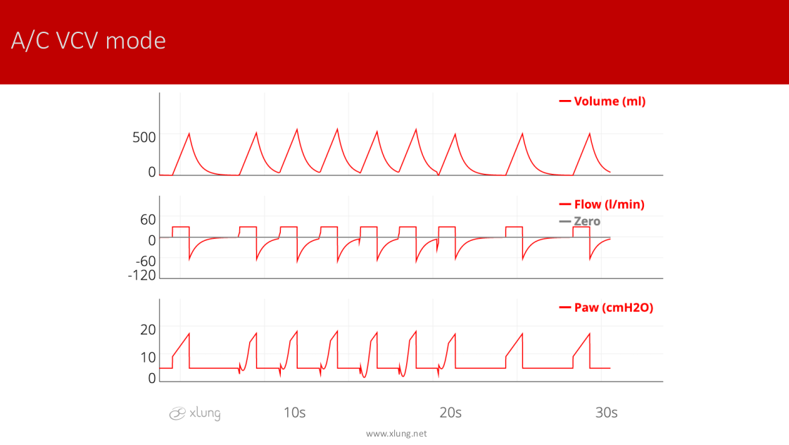
Figure 10. A/C-VCV mode. Settings: RR min: 15 bpm, VT: 500ml, Flow 30l/min, Ti: 1s, total RR 18 `bpm. In this case, the ventilator is "required" to offer at least 15 cycles per minute, which can be controlled or assisted. If the patient makes no muscular effort, all cycles will be controlled with a total duration of 4 seconds (60s/15rpm); with the Ti programmed for 1s, the ratio I: E would be 1:3 if all cycles were controlled. However, as the patient reaches a RR above that programmed, the expiratory time is variable. Note that the first and the last two cycles were controlled, and all the others assisted. The ventilator provides a controlled breath if the patient does not make any muscular effort within the 4-second window.
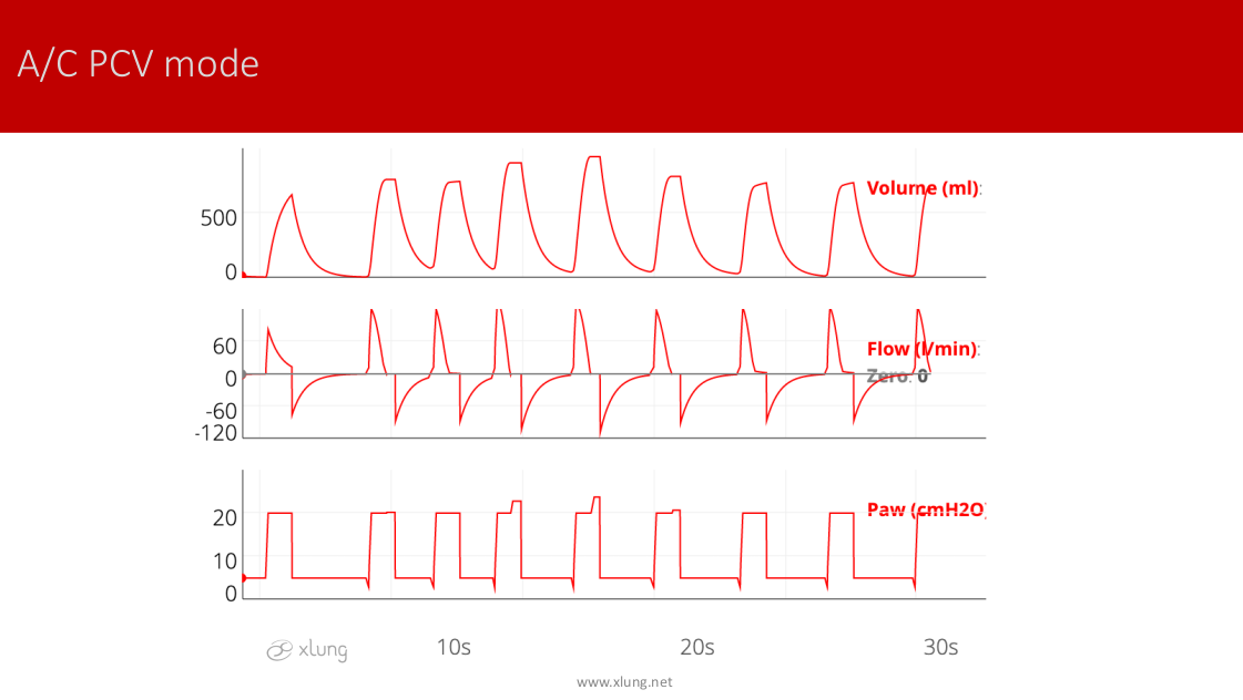
Figure 11. A/C-PCV mode. Settings: RR min: 15 rpm, inspiratory pressure above PEEP (ΔP) 15cmH2O, Ti: 1s, total RR between 18 breaths per minute, pressure sensitivity -2cmH2O. In this case, the ventilator is programmed to offer at least 15 breaths per minute that can be controlled or assisted. If the patient makes no muscular effort, all cycles will be monitored and have a total maximum duration of 4 seconds (60s/15 rpm). If all cycles were controlled with the Ti programmed to 1s, the I:E ratio would be 1:3. However, as the patient reaches a RR above the one programmed, the expiratory time will vary. Only the first cycle was controlled. Observe the variations in VT and the wave flow in response to the patient's demand in the assisted cycles. In the fourth, fifth, and sixth cycles, pressure overshoots occur due to higher patient efforts terminating before the mechanical inspiratory time.
The A/C-VCV mode is normally chosen immediately after tracheal intubation when the patient is sedated or under a neuromuscular blocker. There are two advantages to beginning in this mode rather than A/C-PCV: it is easier to determine respiratory mechanics (refer to the corresponding chapter on this topic) and secondly, and perhaps more importantly, the alveolar pressure is under greater control since this is always determined by the relationship between the VT and the static compliance of the respiratory system. Above all, the use of a protective ventilation strategy, using low VTs in patients with Acute Respiratory Distress Syndrome (ARDS), can be done more easily and safely in A/C-VCV mode. Special attention to airway pressure variation pause in this ventilatory mode should be given. Therefore, the pressure alarm should be adjusted carefully.
The A/C-PCV mode can also be an excellent option for predominantly assisted ventilation when the patient exhibits respiratory muscle effort, for example, during a transition phase in the process of weaning from mechanical ventilation. Special attention, however, should be given to monitoring the VT in this ventilatory mode. The alarm for VT minimum and maximum should be carefully adjusted.
For patients that exhibit good recovery from an underlying disease and sedation is reversed, the PSV mode is commonly employed, where there are only triggers by the patient. In this example all cycles are assisted with the addition of pressure support, as shown in Figure 12.
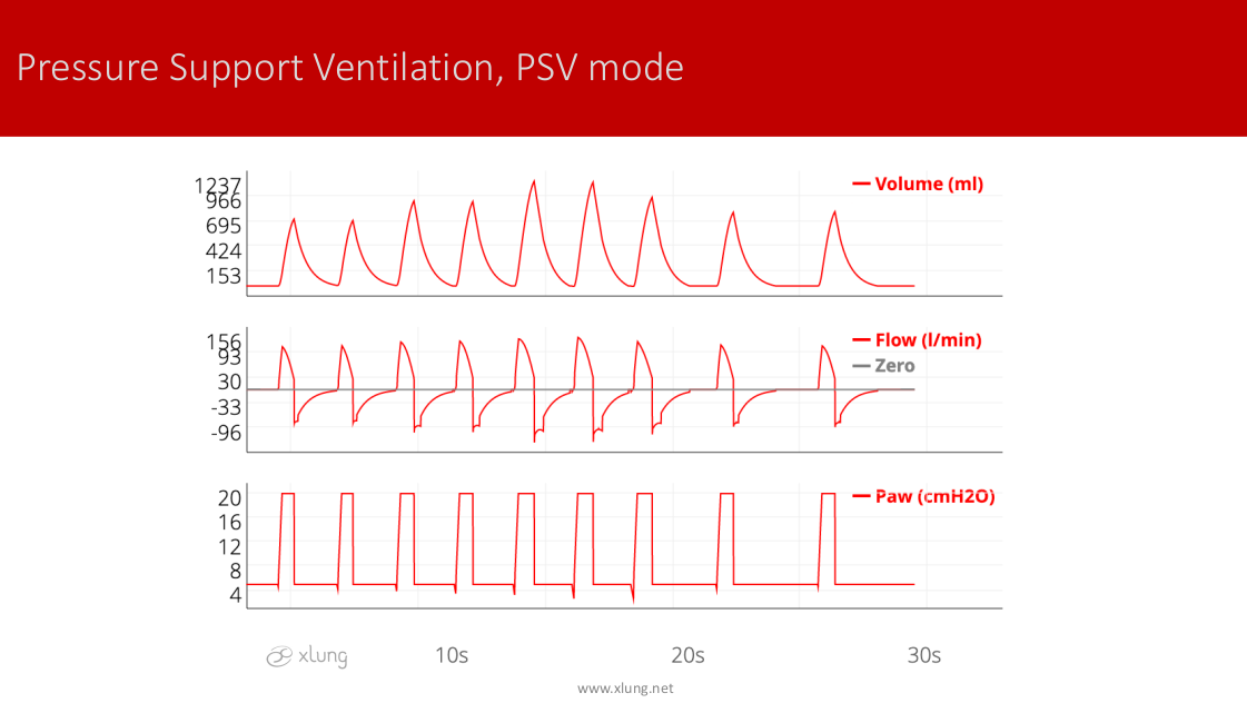
Figure 12. PSV mode. There are no controlled cycles, only assisted ones. Settings: PS above PEEP: 15cmH2O and cycling off criteria: 25% of the peak inspiratory flow in each cycle. Note that. VT, flow, and inspiratory time can differ on a breath-to-breath basis. In this case, the rate, intensity, and duration of the breathing effort increased and later decreased, accompanied by the ventilator response to the patient’s demand.
The PSV mode is typically used for weaning, where PS is reduced gradually while evaluating the patient's ability to adapt to increasingly lower levels until a minimum value is reached, usually between 7 to 10cmH2O or a value just enough to neutralize the resistance impored by the artificial airway. Because only assisted cycles are offered the apnea alarm with backup ventilation should be carefully adjusted.
The SIMV mode with PS is a hybrid of A/C and PSV modes. This mode was developed in the 70's to allow for spontaneous cycles, only with PEEP, interspersed with cycles of VCV or PCV. Currently, PS is routinely used in this mode. A minimum RR is programmed with cycles in VCV or PCV. For example, setting a RR of 6bpm, the ventilator divides a minute into 6 time windows of 10 seconds each. Within each of these windows, the ventilator should offer a respiratory cycle that may be assisted if the patient makes an effort, or controlled at the end of the time window if the patient does not trigger the ventilator. Figure 13 illustrates operating in this mode.
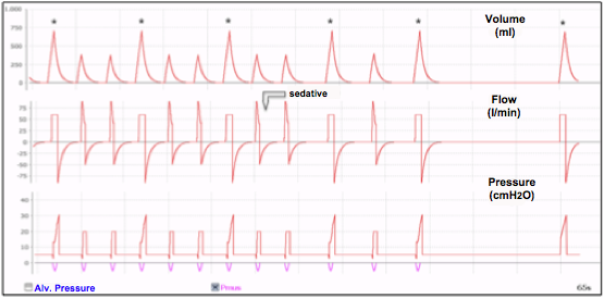
Figure 13. SIMV-VCV mode with PS, recording of one minute. Settings: RR: 6 bpm, PS of 15cmH2O. The ventilator divides one minute into 6 equal time intervals of 10 seconds each, requiring a VCV type cycle for each. This is the type used if the patient makes an effort capable of triggering a cycle within the window of the time interval, or it is controlled and given at the end of that time interval if the patient does not. Note that in this particular case the VT in the cycles with PS are lower than the VCV cycles marked with an "*". The last cycle is controlled type due to apnea that the patient presented after administration of a sedative (arrow).
The SIMV mode, with PS, is widely used. It has the advantage of ensuring a minimum RR where it can establish a fixed VT (SIM-VCV) or a constant pressure in the airway with time cycling (SIMV-PCV). A major disadvantage is the complexity of its settings and the difficulty of recognizing the differences between cycles with PS and those in VCV or PCV.
The table below summarizes the main characteristics of basic ventilatory modes.
Table 1. Main characteristics of the basic ventilatory modes
| Modes/Parameters | AC-VCV | A/C-PCV | PSV | SIMV+PS |
|---|---|---|---|---|
| Principal adjustable variables | Volume, flow and Ti | Airway pressure and Ti | PS | Same as for A/C (VCV or PCV) + PS |
| Types of cycles | Assisted and Controlled | Assisted and Controlled | Assisted | Assisted and Controlled |
| Trigger | Time or patient | Time or Patient | Patient | Time or Patient |
| Control of inspiration flow | Total | Pressurization flow (Rise time) | Pressurization flow (Rise time) | |
| Control of Ti | Yes | Yes | No | Only in programmed cycles |
| Cycling Criterion | Volume | Time | % of peak flow | Volume or time + % of peak flow |
| Main Advantage | Control of VT and alveolar pressure | Greater synchrony of flow and VT | Useful in weaning | Minimum RR guaranteed |
| Main Disadvantage | Lack of synchrony in the assisted cycles | VT and, thus, alveolar pressure not guaranteed | VT not guaranteed | Complexity of settings |
Ti: inspiratory time; trigger time = ventilator
As one can see, the basic ventilatory modes have limitations, often resulting in lack of patient-ventilator synchronization. On the other hand, a detailed understanding of their functionality allows the vast majority of patients to be ventilated satisfactorily.
New ventilation techniques have been developed. These include hybrid modes that mix, for example, characteristics of A/C-VCV and A/C-PCV modes, such as Pressure Regulated Volume Control (PRVC), Volume Assured Pressure Support Ventilation (VAPS) and AUTOFLOW®. There are also modes that offer airway pressure in proportion to muscular effort of the patient and include: Proportional Assisted Ventilation (PAV), Automatic Tube Compensation (ATC), Neurally Adjusted Ventilatory Assist (NAVA) modes, and mechanisms for self-adjustment of the PSV (Volume Support Ventilation). Although promising, most of these methods have not yet been incorporated into the day-to-day use of mechanical ventilation and there exists little evidence of their superiority over basic modes when compared to the relevant clinical outcomes such as duration of mechanical ventilation and survival. The methods that favor greater patient-ventilator synchronization will be specifically discussed in the corresponding chapter on this topic.